1. Introduction
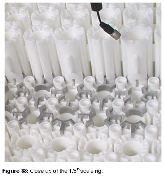
Whole core modelling is another approach of British Energy’s graphite core safety case strategy to determine the extent of tolerable cracking in the graphite core. The whole core experimental rig work was originally based on a 1/8th scales model of a HPB/HNB reactor cores being the lead stations. The 1/8th scale core rig was developed in stages, firstly as a single scale rig, then a full array, testing channel distortions, and more recently as a core with a limited number of doubly cracked bricks. The rig was made up of simplified fuel and interstitial brick components scaled by a factor of 1:8, however, the clearance were maintained at full scale to facilitate displacement measures.
2. Original 1/8th Scale Core Rig
The 1/8th scale core rig design simplified the HPB/HNB components by incorporating keys into the bricks: the fuel brick included two integral bearing keys and the interstitial brick included four integral keys. These simplified components represented the primary keying system and allowed it to transmit the loads in a representative manner. The secondary keying system, comprising filler and spacer keys, were omitted. An assessment of the effect of the primary and secondary keying systems was made using computational models. The outcome suggested that the spacer and filler keys could be omitted, as the rigidity of the AGR core is only slightly effected.
The full scale key /keyway clearances were maintained in order that the maximum displacements observed were equal to those possible in the reactor core. Unfortunately, this meant that other factors i.e. rotations and key engagement were not representative. Had the 1/8th scale core rig been completely scaled i.e. having clearances of the order of 0.13 – 0.19mm, it would not have been practical to observe the displacement effects.
The 1/8th scale core rig was not intended to model the effects of doubly cracked bricks. As the core rig is tested with increasing fuel brick cracking, the full scale key / keyway clearances cause the displacements observed to become overly pessimistic. Single layer tests to determine the upper bounds of possible displacements with varying percentages of doubly cracked bricks showed that key disengagement occurred much earlier than would be expected in real AGR geometry.
The results of this represent a very onerous worst case scenario – the bricks were on a smooth base with no end face keying to constrain them, The rig was no longer valid as the full scale clearances allowed unrepresentative disengagement.
3. New 1/4th Scale Core Rig
A new scale core rig was developed to replace the original 1/8th scale core rig, as the inherent pessimisms were no longer able to represent the proposed cracking scenarios accurately.
The new scaled core model had to meet two criteria; firstly it had to be easy to manipulate and secondly it had to be easy to monitor. A full array full height core would have taken too much time to build, and due to the ease of handling scaled fuel bricks it would make a scaled model faster to assemble. Making the bricks to small however, would reduce the clearances beyond measurable means. Extracting accurate data from tests would have become more difficult with smaller components, as the effects of instrumentation error would have been greater. The possible scale factors were reviewed for a flly scale core rig and the smallest practical scale was derived to be approximately a quarter scale. Although tolerances of 0.02 mm could be theoretically achieved to produce a fifth scale core rig, in reality the experimental techniques available to analyse the results were not sufficiently accurate.
The HPB/HNB reactor core design was considered as the prime candidate for the new scale model being the lead stations. However, the complexity of the core geometry was very difficult to model accurately whereas the HRA/HY1 reactor core design has a much simpler core geometry. Still, the core geometry was simplified further for the scale rig due to economic constraints. The fuel brick, interstitial brick and loose key designs were taken from the central layers of the reactor core and these were replicated to fill the core. The rocking features were omitted from the scaled fuel brick – the effect of these was not deemed to be significant for the initial test programme. The selected components were accurately scaled down, minimising the potential pessimism in rig results.
No attempt to scale density or friction was carried out as the model was principally for extreme displacements under static loading. Therefore, the most important material property was the dimensional stability. It was necessary to select a material which would maintain the tight tolerances set. A range of potential polymer options were researched, however the available manufacturing techniques could not meet the tolerances required to produce an accurate quarter scale rig. Previous experience with aluminium extrusions for doubly cracked bricks in the 1/8th scale model had been promising and this avenue was pursued. The method allowed the bricks to be machined in the final stages to meet the requisite tolerances.
The quarter scale rig was finally designed to model the full height full array core i.e. 24 brick diameter and 12 layers high. A full array core was estimated 35 tonnes. The quarter scale core was restrained by the outer ring of fuel bricks in the rig in much the same way as the reflector bricks restrain the real core. Additional stiffeners in the form of 15mm thick steel plates were also used to prevent the core periphery from distorting during tilting. The mass of the complete rig was estimated to be 45 tonnes.

4. Rig Testing
The quarter scale core rig does not model the transient thermal expansion and contraction of the core – it is purely a geometric model used for static testing. The tests were designed to induce geometric channel distortions by tiling the rig, applying a uniform load to the core, to generate extreme displacements. The applied load was sufficient to displace the bricks, using up all the available clearances and allowing the graphite channel distortion to be observed. The octagonal shape (see above) was chose to allow the rig to be tiled in any of the eight directions – this enabled both cardinal and oblique loading of the rig to be assessed. Cardinal loading of the rig transmits the load via the interstitial bricks while oblique loading transmits the loads via the bearing bricks.
The actual results and conclusions of the rig analyses can be found separately in References and Further Reading at the end of section.
